
Learn the interfacing Tilt Switch Module in Arduino. The tilt switch is just like a normal switch with a little difference. The tilt switch has a ball inside its tube. On tilting the switch ball will roll down connecting the metal contact and activating the switch. We have connected led with the tilt switch which will be activated by tilting the switch. For this, we will use the Tilt switch module and Arduino UNO board. So, let’s start.
Step 1: Required Components
Tilt Switch module x 1
Generic LED x 1
Breadboard x 1
Arduino Uno Board x 1
Jumper Wires
Step 2: Circuit Time
Firstly, connect LED to digital pin 13 of Arduino. Now, connect the signal pin to the tilt switch module to digital pin 2 of Arduino UNO. Then, connect the VCC pin and GND pin of the tilt switch module to the +5v and GND pin of the board.
Step 3: Code Time
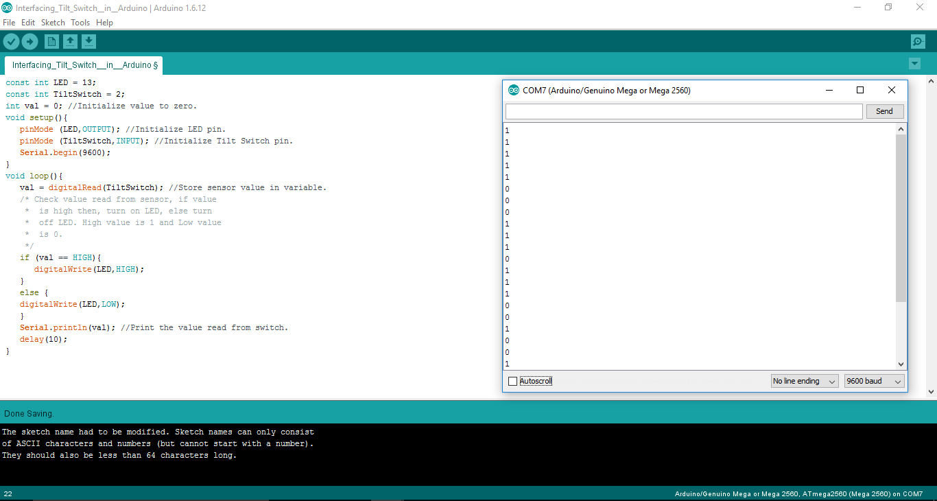
This is code for interfacing the Tilt Switch Module in Arduino. Firstly, initialize pins for tilt switch and LED, then initialize reading to 0. In setup, set LED pin as output and tilt switch pin as an input. Loop will check the reading of the tilt switch. If reading is 0 switch is off and if reading in 1 switch is on. LED turns on when reading is 1 and turns off when reading is 0.
Step 4: Upload the code to Arduino
Upload the above-given code to the Arduino UNO Board after the components are set as per the Circuit Diagram. The LED will turn on when the switch is on and turns off. The screenshot of the output of reading is given below.
Learn more information about uploading code to Arduino Uno.