How to interface the DS3231 RTC Module in the ESP8266 WiFi Module. Currently, we are using the DS3231 RTC Module and ESP8266 ESP12E WiFi Module. Setup and display the time of DS3231 on Serial Monitor.
First, let’s start with the basics of the DS3231 Real Time Clock Module.
Operating Voltage: 3.3 – 5V
Current: 15mA
Accuracy: ±2ppm at 0°C to +40°C and ±3.5ppm at -40°C to +85°C
Digital Temp Sensor Output: ±3°C Accuracy
Alarms: Two times of a day
Battery Backup for continuous timekeeping
Integrating Adafruit RTC Library in Arduino IDE.
- Download Adafruit RTC Library Zip file from below given link
- Go to Sketch > Include library > Add .zip Library
- Select the downloaded zip file
- If the Library is successfully added, Arduino IDE will show “Library added to your libraries. Check Include Library menu” on the status bar.
Learn more information about the RTC Library.
Step 1: Required Components
DS3231 RTC Module x 1
ESP8266 (ESP-12E) WiFi Module x 1
Jumper Wires
Step 2: Circuit Time
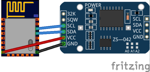
Make a circuit as per the given diagram. In Real-Time Clock there are six pins available. We will be using only four pins. Connect the pins as below given.
VCC to 3.3V
GND to Ground
SDA to GPIO 4
SCL to GPIO 5

Step 3: Code Time
This is code for interfacing DS3231 RTC Module in ESP8266 WiFi Module. First, we include the necessary libraries for Real-Time Clock and ESP8266 WiFi. In setup, the Serial Monitor is begun at 115200 Baud and Date-Time is set according to system time if the time of RTC is not set. Also, SSID and Password of your WiFi to connect. In the loop, we fetch current date and time from Real-Time Clock and it is displayed in the serial monitor. To reset the Real-Time Clock, remove all wires from WiFi Module and also battery from Real Time Clock for 10 seconds. Then reassemble the circuit and upload the program again.
Step 4: Upload the code
Set components as per the Circuit Diagram and upload the code to the ESP8266 WiFi Module. DS3231 Real Time Clock will provide time to ESP8266 and it will display in Serial Monitor.
