
Learn the interfacing Analog Joystick Module in Arduino Board. Joystick module is the Analog module. Analog Joysticks is useful to add axis based controls. For this, we will be using Analog Joystick and Arduino Uno. So, let’s start.
Step 1: Required Components
Joystick Module x 1
Breadboard x 1
Arduino Uno Board x 1
Jumper Wires
Step 2: Circuit Time
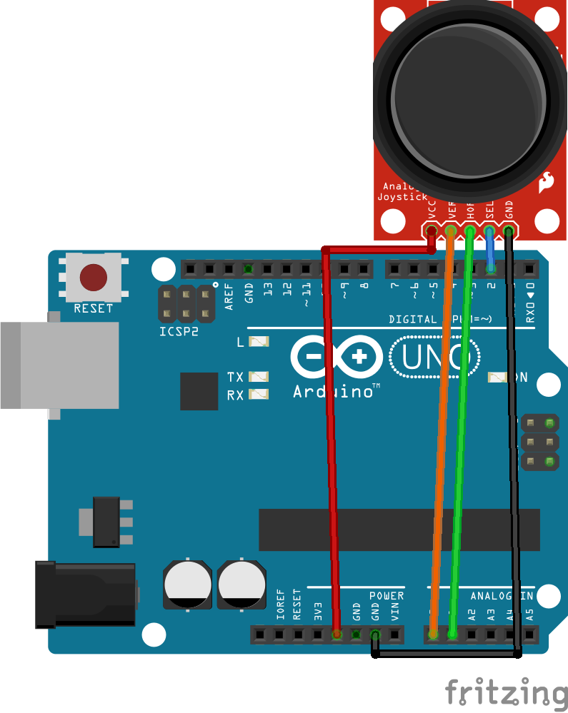
This is a circuit diagram of the Analog Joystick module in Arduino. There are five pins in analog Joystick Module VCC, GND, Key, X, and Y. X and Y are Analog pins and Key is digital. The key will be used when Joystick is pressed. Connect VCC of the module to +5v of Arduino and GND of the module to Arduino Ground. Now, connect X to Analog pin A0 and Y to Analog pin A1 of Arduino. Connect Key to Digital pin 2 of Arduino.
Step 3: Code Time
This is code for interfacing analog Joystick Module in Arduino. First initialized the pin numbers of Joystick Module. In setup, the Serial Monitor is started at 9600 Baud and initialized Joystick pins as input. In the loop, read the button state and stored it in a variable. Print the values to the Serial Monitor.
Step 4: Upload the code to Arduino
Set the components as per the Circuit Diagram and Upload the above-given code to the Arduino Board. It will show the output of X and Y on the serial monitor.
Learn more information about uploading code to Arduino Uno.