Learn using SPI in Arduino. SPI (Serial Peripheral Interface), establishes communication between multiple peripheral devices or microcontrollers. The SPI interface bus exchanges data between microcontrollers and small peripherals such as shift registers, sensors, and SD cards. It uses the different clock and data lines along with a select line to choose to communicate with which device.
Generally, there are three lines common to all the devices, MISO (Master In, Slave Out) and MOSI (Master Out, Slave In). For device selection, we use SCK Clock Line and fourth one SS (Slave Select). SS pin will switch devices when connecting multiple devices. Now let’s see how SPI Communication in Arduino works.
Different library Functions of SPI in Arduino
SPI.begin()
- A call to this function will initialize SCK, MOSI, and MISO pins. For the SS pin, the configuration is done manually.
SPI.usingInterrupt(interrupt)
- If your program is performing SPI transactions within an interrupt, this function will register the interrupt number or name with the SPI library. This allows beginTransaction() to prevent usage conflicts.
SPI.beginTransaction(SPISettings(clock speed, MSBFIRST, SPI_MODE0))
- This function starts with the SPI bus. SPI is configured for using the clock, data order, and data mode.
- The data order can be from MSBFIRST (Most Significant Bit First) or LSBFIRST (Least Significant Bit First).
- The data modes will range from 0 to 3, and it will be set using SPI_MODEx (x = 0,1,2,3).
- The clock speed determines the maximum speed SPI slave device can accept.
digitalWrite(SSpin, level)
- Most SPI devices define a transfer of multiple bytes.
- You need to write the SS pin before the transfer begins (most chips use LOW during the transfer) and write it again after the last byte, to end the transfer. See below for more SS pin details.
SPI.transfer(data)
- Calling this function will transmit data byte from master to slave, and simultaneously receive a byte from slave to master.
- In SPI, transmission and receiving will occur at the same time, but receiving byte is generally ignored. If the reception is required, transmit bytes 0 to 255.
SPI.endTransaction()
- This function stops the usage of the SPI bus.
- We will call this function after de-asserting the chip select and allow other libraries to use the SPI bus.
Circuit Time
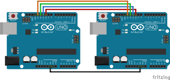
- This is a Circuit Diagram for communication of SPI in Arduino.
- Firstly, connect pin 13 (SCK pin) of both Arduino.
- Now, connect pin 12 (MISO pin) of both Arduino.
- Then, connect pin 11 (MOSI pin) of both Arduino.
- Also, connect pin 10 (SS pin) of both Arduino.
- Finally, connect both Arduino board to common ground.
Code Time
Master Arduino for SPI Communication Code
Slave Arduino for SPI Communication Code
Upload the code to Arduino
Thus now you can Upload the above-given code to two Arduino Boards and it will transfer “Hello World!” using SPI Communication.
Learn about uploading code to Arduino Boards.


Thanks for such a good tutorial , especially the way you stored array of charcters in a buff. But please let us know how the slave send back data to Master after recieving from master. Further we want the master to send data to Slave and then Slave see the data and decide to send a value or other depending upon what Slave recieved from Master .
For Example if Slave recieve ‘a’ the reply to master ‘100’ and if Slave recieve ‘b’ then reply an amount ‘200’ to Master